


Electromagnetic flowmeter is a flow measurement device based on Faraday's law of electromagnetic induction. The working principle of this instrument is to utilize the electromotive force generated when a conductive fluid flows in a pipeline perpendicular to the magnetic field direction. Specifically, when a conductive fluid flows in a pipeline, due to Faraday's law of electromagnetic induction, an electromotive force proportional to the flow velocity is generated in the fluid. This electromotive force will be detected by the electrode and transmitted to the converter through the electrode. The function of the converter is to convert the detected electromotive force into an electrical signal output proportional to the flow rate. By measuring this electrical signal, we can calculate the fluid flow rate through the pipeline.
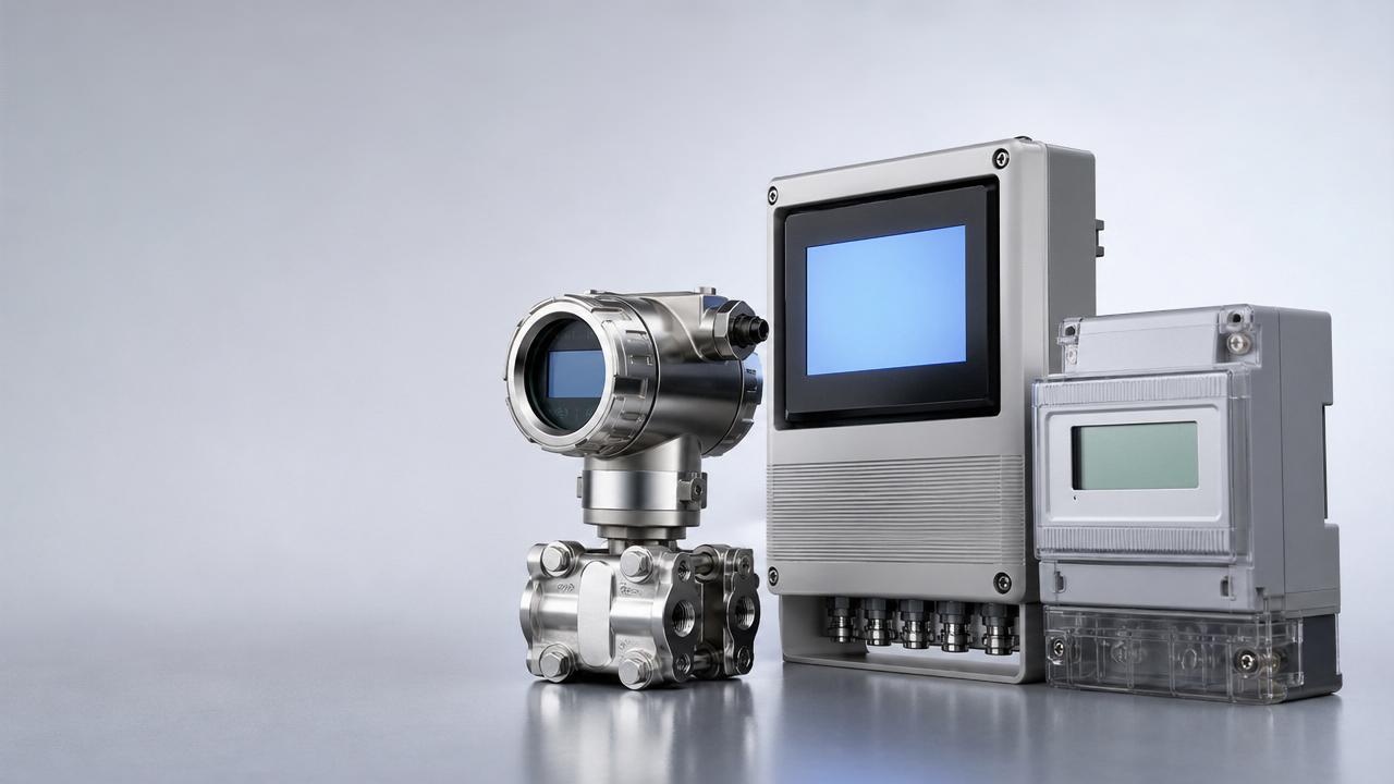
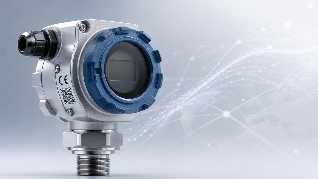
The main components of an electromagnetic flowmeter include a measuring tube, an excitation coil, electrodes, and a converter. The measuring tube is a channel for fluid flow, the excitation coil is used to generate a magnetic field, the electrode is used to detect the electromotive force in the fluid, and the converter is responsible for converting the electromotive force into an electrical signal. These components work together to ensure that the electromagnetic flowmeter can accurately measure fluid flow.
The advantage of electromagnetic flowmeter lies in its wide measurement range and high accuracy. It is not affected by changes in fluid density, viscosity, temperature, pressure, and conductivity, making it highly reliable in various industrial applications. This flowmeter is suitable for measuring various conductive fluids, such as water, acid, alkali, and salt solutions. Due to its unique measurement principle and structural design, electromagnetic flowmeters have been widely used in industries such as chemical, metallurgical, power, water supply, and sewage treatment.
In addition, electromagnetic flow meters also have the characteristics of fast response speed and low maintenance costs. It can monitor real-time changes in fluid flow rate, which is crucial for process control and flow monitoring. Due to its non-contact measurement method, electromagnetic flow meters hardly cause any obstruction or pressure loss to fluid flow, which has led to their increasing application in the food and beverage industry. Meanwhile, due to the fact that the measurement of electromagnetic flowmeter is not affected by solid particles or bubbles in the fluid, it also performs well in the measurement of mud and fluids containing suspended solids.
Correct installation method of electromagnetic flowmeter
1. Horizontal and vertical installation
Sensors can be installed horizontally and vertically, but it should be ensured to avoid the influence of sediment and bubbles on the measuring electrode, and the electrode axis should be kept horizontal. When installed vertically, the fluid should flow from bottom to top. The sensor cannot be installed at the highest position of the pipeline, as this position is prone to the accumulation of air bubbles.
2. Ensure full pipe installation
Ensure that the flow sensor is filled with the measured fluid in the pipeline during measurement and that there is no non full pipe state. If the pipeline is not full or the outlet is empty, the sensor should be installed on a siphon tube.
3. Installation between bends, valves, and pumps
To ensure measurement stability, a straight pipe section should be installed before and after the sensor in the intelligent electromagnetic flowmeter. If this is not possible, a stabilizer should be used or the cross-sectional area of the measurement point should be reduced.
4. Sensors cannot be installed at the inlet of the pump
To avoid negative pressure, the sensor should not be installed at the inlet of the pump, but at the outlet of the pump.
5. The inlet and outlet straight pipe sections of the sensor
An ideal installation location should be chosen with sufficient straight pipe sections before and after the measurement point.



 1259 New National Standards Take Effect in May 20261259 new national standards effective May 2026 mandate GFAAS, LC-MS/MS & GC-MS for compliance—key for exporters, labs & instrument suppliers.
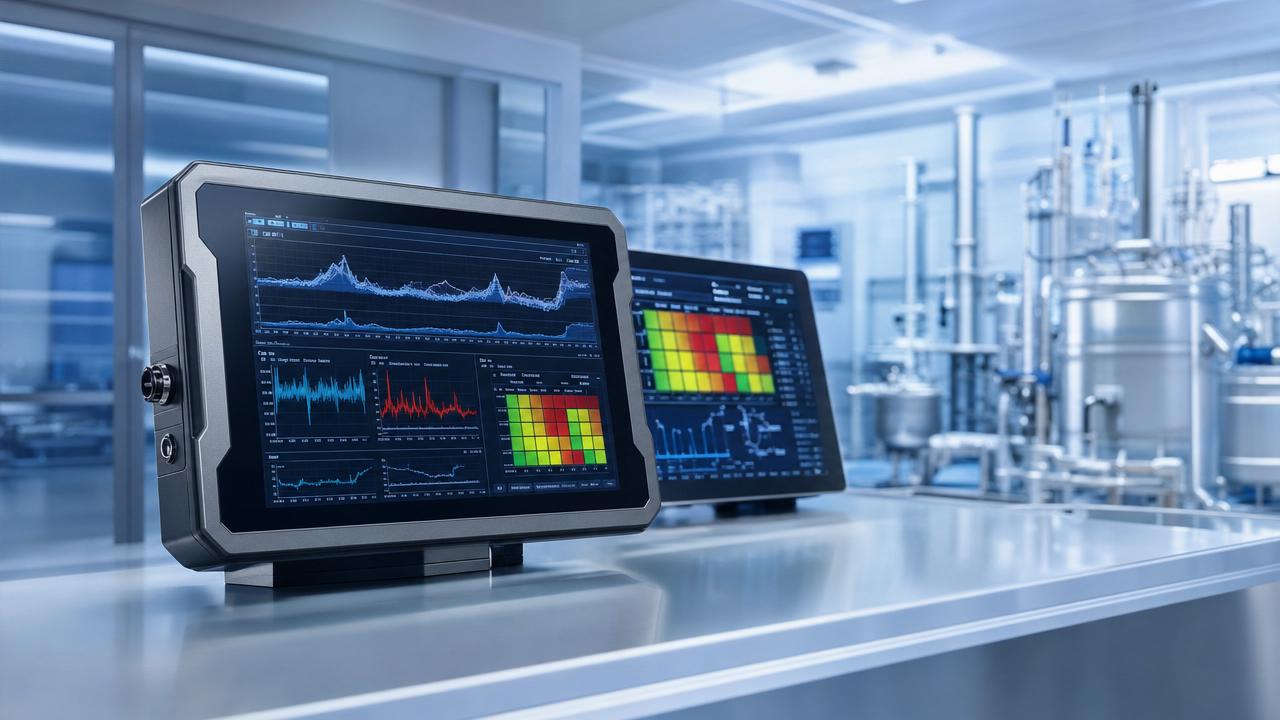
 GWM Patents AI-Driven Multi-Screen Quality Switching for Vehicle HMIsGWM's AI-driven multi-screen quality switching patent unlocks adaptive display tech for industrial HMIs, DCS stations & explosion-proof touchscreens — watch for certified deployments.
 US-China Tariffs Unified at 10% for InstrumentsUS-China tariffs on instruments unified at 10%—boosting cost efficiency for industrial process instruments, environmental monitoring equipment & energy meters. Act now.
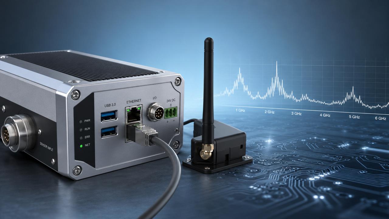
 EN 61000-6-4:2026 Enters Force for Industrial EMC ComplianceEN 61000-6-4:2026 is now mandatory for industrial EMC compliance — stricter 1–6 GHz emissions & dynamic AI-device testing. Act now to avoid EU market delays.
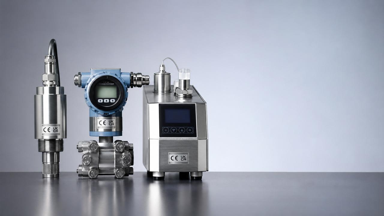
 New China Export Rules for Instruments Effective May 2026New China export rules for instruments require CNAS-issued CE/UKCA reports by May 2026 — ensure compliance now to avoid EU/UK shipment delays.
 EU CE-EPD Digital Compliance Label Mandatory from May 2026EU CE-EPD digital compliance label becomes mandatory for instrumentation exports from May 2026 — discover how Chinese OEMs, suppliers & EMS providers can prepare now.

Chat Online